Team Updates
We did a new recruiting push for IAP and onboarded 9 new members! It’ll take a little while to onboard them, but between Herbie and our new navigations co-lead Jacob, we think we’ll have the bandwidth to both code and teach. We will be working hybrid for IAP so that we can accommodate people who haven’t yet arrived on campus.
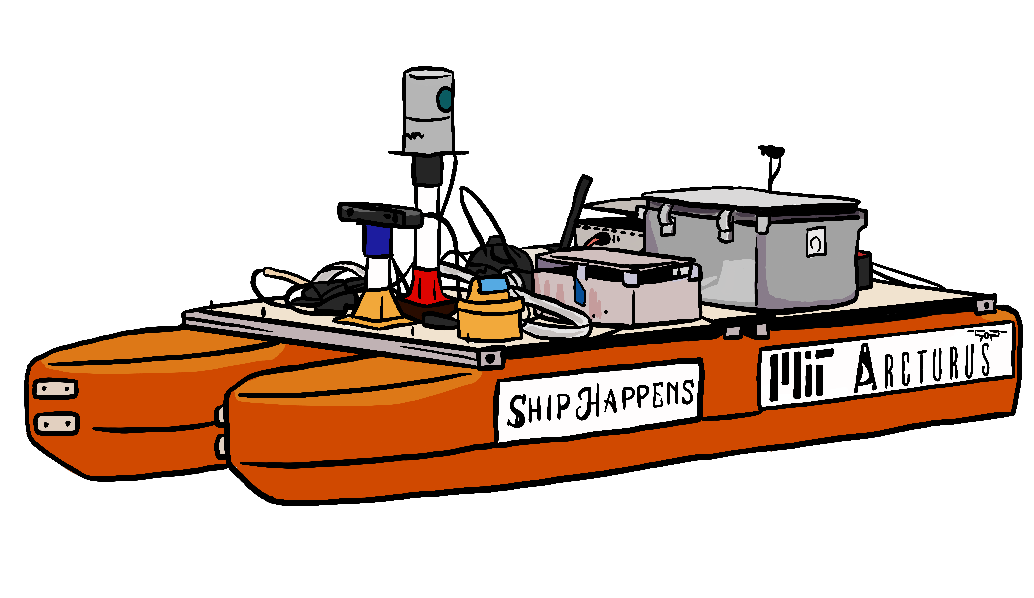
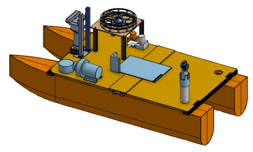
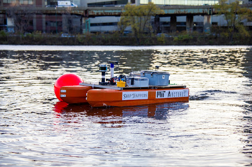
We will be continuing to work using our test boat Athena, while Ship Happens is under construction. Our Gazebo simulation will enable those working remotely to keep working without access to the hardware.
ROS Display: Youry Moise, Herbie Turner
We’re working to develop a dashboard that displays real-time sensor data collected from ROS.
ROS stands for Robot Operating System; is a software middleware suite that allows us to receive information from a robot’s sensors and send it instructions based on that information. It has several “nodes” that are either publishers (the ones that send data), subscribers (the ones taking it in), or both. The data is transmitted in the form of discrete “topics”. Topics can include the depth registered, temperature, position, velocity, and other pieces of information.
Data can be streamed in real-time from ROS topics or stored and made accessible via a “rosbag," which periodically collects all the sensor data. This data may be published over 100 times per second for one topic. With dozens of topics all publishing at this rate for several minutes uninterrupted, rosbags typically become extremely large, amounting to 15 gigabytes of storage after just 5 minutes of operation.
Although it is possible to access the data from the command line it is not always convenient. Some of the commands aren’t very intuitive and visual data can only be displayed as numerical arrays. As a solution, ROS offers a package called RVIZ which can display standard ROS topics including 2D and 3D data. However, RVIZ lacks the capability to easily display some of our custom messages as well as the ability to easily control actuators on the vehicle.
To achieve this with our own dashboard, we are using Qt, software that expedites GUI development by providing libraries for widgets such as buttons, labels, tabs, and forms. PySide2 is what allows us to use the coding language, Python, to interact with those widgets.
The plan is to have 5 main tabs. The first will be an overview tab that gives a summary of the most important topics, including the 3D Map, 2D Map, Vehicle State, and Front Camera View. It will also contain a queue of tasks that the robot is planning to execute. The rest of the tabs will be “Sensors," “Perception," “Mapping," and “Pilot," and will display the appropriate information.
Boat Positioning: Wendy Sun
For an autonomous vehicle, object positions are relative to the boat’s current position. Therefore, we need to constantly have an accurate idea of where the boat currently is located, in order to put every other object in the correct world view.
There are four sources of positioning data: 1) ZED camera odometry; 2) Ardupilot; 3) Velodyne LiDAR odometry; 4) Reach M2 RTK receiver.
I started off with writing a positioning node that takes in only the ZED camera data. The positioning node assumes that the boat starts at point (0,0) on a Cartesian plane, and that x-axis points towards the boat’s starboard while the y-axis points towards the front.
After we successfully tested the ZED positioning node on data from last year’s competition as well as this year’s testing, I then moved on to writing a combined node that takes in both the ZED camera data and the Pixhawk data. Currently, I wrote two versions of the combined node: 1) simply taking the average of the ZED and Pixhawk data; 2) using robot_localization that can process multiple inputs from sensors.
The next step is to test the two combined nodes, decide which one works better, and then use the chosen approach to combine all four sensor inputs.
MOOS-IvP and ROS Integration: Toya Takahashi
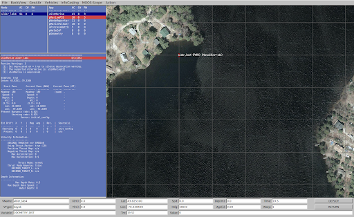
We are currently using ROS1 for our autonomy code, but we wanted to experiment with MOOS-IvP since many marine research labs at MIT use it, the software is more specific for marine vehicles, and it has the potential to increase our parallel processing power. Similar to ROS, MOOS-IvP is a bundle of open-source C++ modules, but specifically for autonomous marine vehicles. MOOS acts as a middleware that connects many applications together including MOOSDB (the database), IvP Helm (determines the behavior of the marine vehicles), and others. New applications can be made with C++ using the MOOS-IvP libraries, be deployed together in a single mission using MOOS, and share their data via MOOSDB. To get started on MOOS-IvP, we completed lab assignments for MIT’s graduate class 2.680 Unmanned Marine Vehicle Autonomy, Sensing and Communications. In the picture below, we have a sample mission from one of the lab assignments running on an application called pMarineViewer.
Furthermore, Professor Michael DeFilippo, a research engineer at MIT Sea Grant, has been working on a ROS node and MOOS application that connects the two software. His software serves as a bridge between MOOS-IvP and ROS, allowing ROS to publish MOOS variables into MOOSDB and vice versa. We have been and will continue to work with Professor DeFilippo to experiment with how we can integrate both ROS and MOOS-IvP to increase our parallel processing power and combine the strengths of the two software.
Perception: Evelyn Zhu, Bruke Wossenseged
There are several different tasks that our Autonomous Surface Vehicle (ASV) must be able to complete as part of the RoboBoat competition. Example tasks include navigating around obstacles like buoys and poles, and locating a target to shoot water at. One necessary component of our ASV is the ability to detect the different objects that will be in the various tasks. This is the Perception system of the ASV, and it is one of the projects within the Navigations subteam. We worked on two sub-projects as part of this system: 1) creating a labeling workflow and 2) developing an object detection model.
Generally speaking, before we are able to train a model we first have to gather some data. In our case, we were looking for image data that was specific to the types of objects in the RoboBoat competition (e.g. buoys, poles, and a dock) and that included labeled bounding boxes of the objects. While we were able to find some existing datasets on the Internet, we discovered that the data contained mislabeled images, and consequently, our initial object detection model was not very accurate. As such, we wanted to generate labeled data on our own, which is where the labeling workflow comes in.
Our team had access to some videos from online and from our own boat tests that captured the objects we would see in the competition. Using those videos, what we would need to do is generate bounding boxes for each frame, and we decided to use MATLAB for this labeling process. There are other labeling softwares out there, like Label Studio which has a nice UI and is free for anyone to use. However, while MATLAB is proprietary, thankfully MIT’s license covers most of the toolboxes that MATLAB offers. Moreover, MATLAB has some very nice built-in software, like the Video Labeler app, which we used to help us automate the labeling process.
The Video Labeler app provides a straightforward way to generate rectangular bounding boxes in video data, especially with the built-in algorithms like Point Tracker and Temporal Interpolation. With the Point Tracker algorithm, all I would have to do is hand-label the object in the initial frame, and the software would be able to track the object in the following frames. Temporal Interpolation was a neat algorithm as well. By hand-labeling just a few key frames, we are able track the bounding boxes over time of an object that comes in and out of frame. Using these tools in MATLAB, we were able to generate a training dataset with new labeled data.
So far, we have been using the YOLOv5m model architecture for training. To compromise accuracy and time to train, we moved forward with this model as compared to larger versions of YOLOv5. This model contains 21.4 million parameters and has an mAP (accuracy) score of 45. To train this model, data needs to be arranged in a certain format with separate text files for each image indicating the class and locations and size of the bounding boxes. As noted, the first training of this model resulted in poor accuracy due to issues with data labels, but we hope that with our updated data this can be vastly improved. We will also further examine implementing the larger versions of this model.
For guidance on using data and training the model, see the README of this github repo.
The next steps include training our model on this dataset and seeing how well it performs. We also have some video data that hasn’t been used yet from which we can generate more labeled data, and this shouldn’t be too difficult a task since the labeling workflow is already set up. We expect to complete these within the next week.
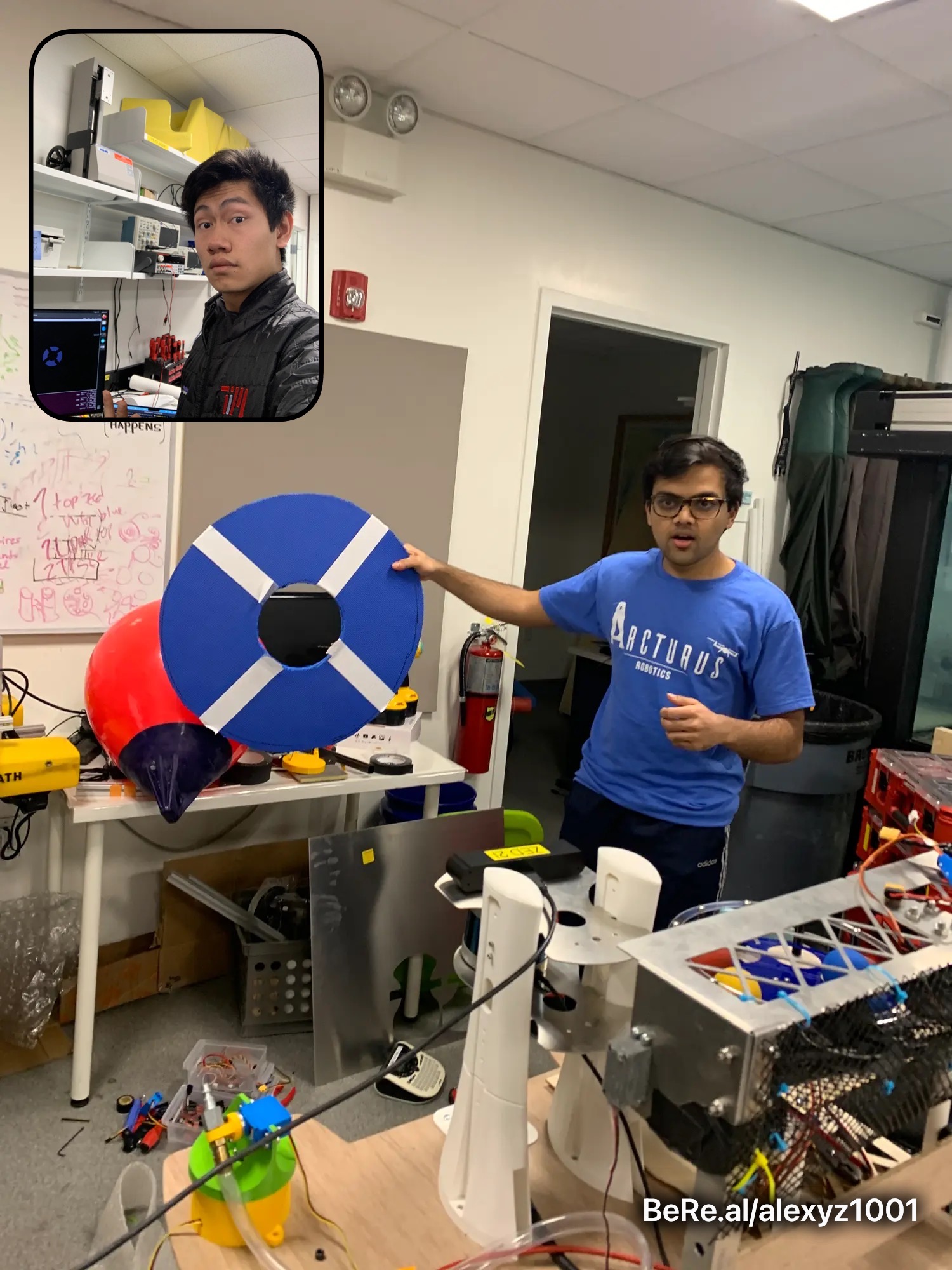
Water Gun Target Detection: Aarush Gupta, Alexander Zhang
The main goal of the water gun task is to shoot a water gun through a target, which fills up a bucket. The target is a blue disc with two perpendicular white lines running across diameters of the disc. Where the two white lines intersect is a hole where the target attaches to a pipe that connects to a bucket. Water needs to be shot into this hole in order to fill the bucket up with water.
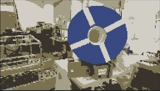
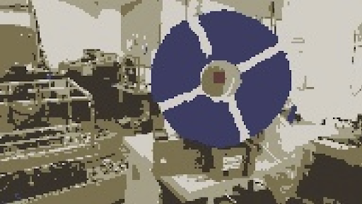
The ZED-2 camera which our vehicle is equipped with provides both RGB and depth data. RGB data can be used to detect the target: we apply a threshold for the blue component of each pixel value (in HSV specifically, which is a better format for distinguishing colors) — then, all pixels which meet a certain blue “threshold” can be considered to be part of the target. Before doing this, we also use the depth data as a mask: all pixel values which are detected to be beyond a certain threshold distance away are ignored in order to minimize unintended noise due to distant objects. After the pixels that correspond to the target are detected, we take the median of their locations to approximate the center of the target.
Our original idea was using an image segmentation algorithm in order to determine the pixels corresponding to the target. While this was functional to some extent, we ultimately decided to use a more simple approach in order to increase robustness and speed, as complex algorithms might not be able to run well in real-time.
After the computer vision side of this task is finished, we will integrate this with the actual water gun by sending target information through ROS — the mechanical water gun will rotate accordingly and fire at the target.
Image segmentation algorithm results:
Creating Simulations in Gazebo: Jenny Zhao
For the RoboBoat 2023 competition, there are 8 total tasks our autonomous boat must accomplish. From simple navigations between buoys to more complicated tasks such as shooting a ball through a target, these 8 tasks make up a specific course that our boat will have to complete.
Before we have our boat designed, built and assembled though, I’ll be working on creating a testing simulation in an application called Gazebo. RoboBoat has given detailed specifications regarding each task. For example, we know each buoy’s color, size and shape and any other obstacle or task details. Using this we can create a very good simulation in Gazebo.
In order to create the simulations in Gazebo, we’ll have to first create accurate meshes in Blendr to represent each obstacle or task object. Taking these object meshes, we’ll be able to put them into task worlds and recreate each task. After creating all tasks, we will combine them into a large world with all the tasks in the same order as presented in the actual competition.
By creating these task simulations first, we will be able to create a boat object and test out our navigation systems for errors earlier, even before the boat has even been completely assembled and built. That way, when the boat is completed, and we start testing in real waters, we will hopefully have less errors and problems to deal with.